
Flow Optimizer® Vaned Spool
Custom flow conditioning spool assemblies for pump suction pipingApplication-specific assemblies developed around the pump, suction-piping geometry and operating envelope.
INLINE FLOW CONDITIONING
Give the pump a better inlet condition.
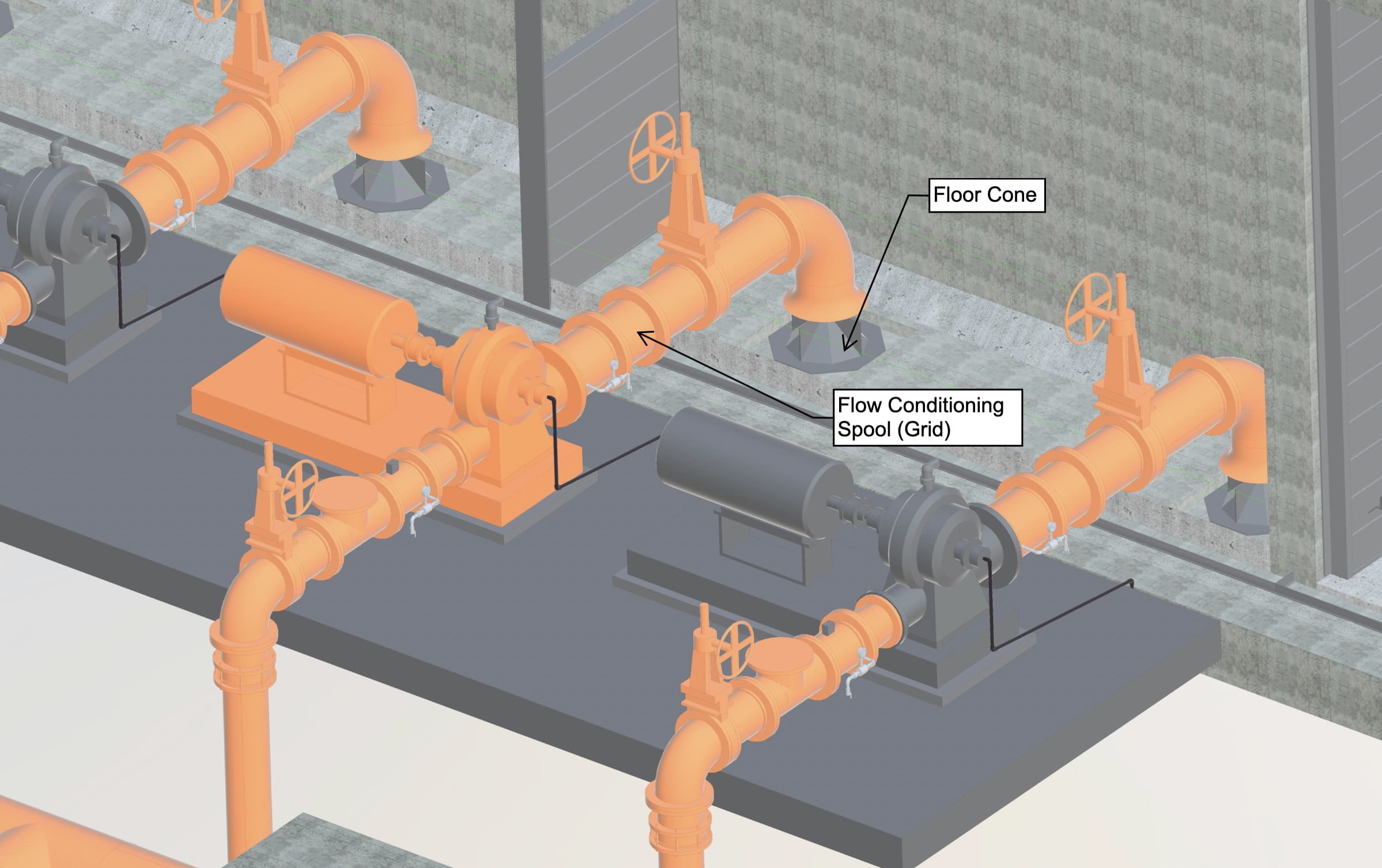
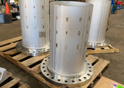
Flow Optimizer® vaned spool assemblies mount in the suction piping, commonly near double-suction split-case pumps. Internal vanes are configured for the application to guide and redistribute incoming flow before it reaches the pump nozzle.
These assemblies are considered where elbows, reducers, headers, limited straight run or other upstream geometry may create uneven velocity distribution, swirl or prerotation. The appropriate geometry depends on the complete piping arrangement and operating range.

What the assembly is designed to address
The objective is to improve the quality and consistency of flow approaching the pump—not simply add another fitting to the line.
More uniform approach flow
Internal vane geometry is designed to redistribute flow approaching the pump suction nozzle.
Manage swirl and directional bias
Application-specific flow conditioning can help address rotational or asymmetric flow introduced by upstream piping.
Designed for the actual system
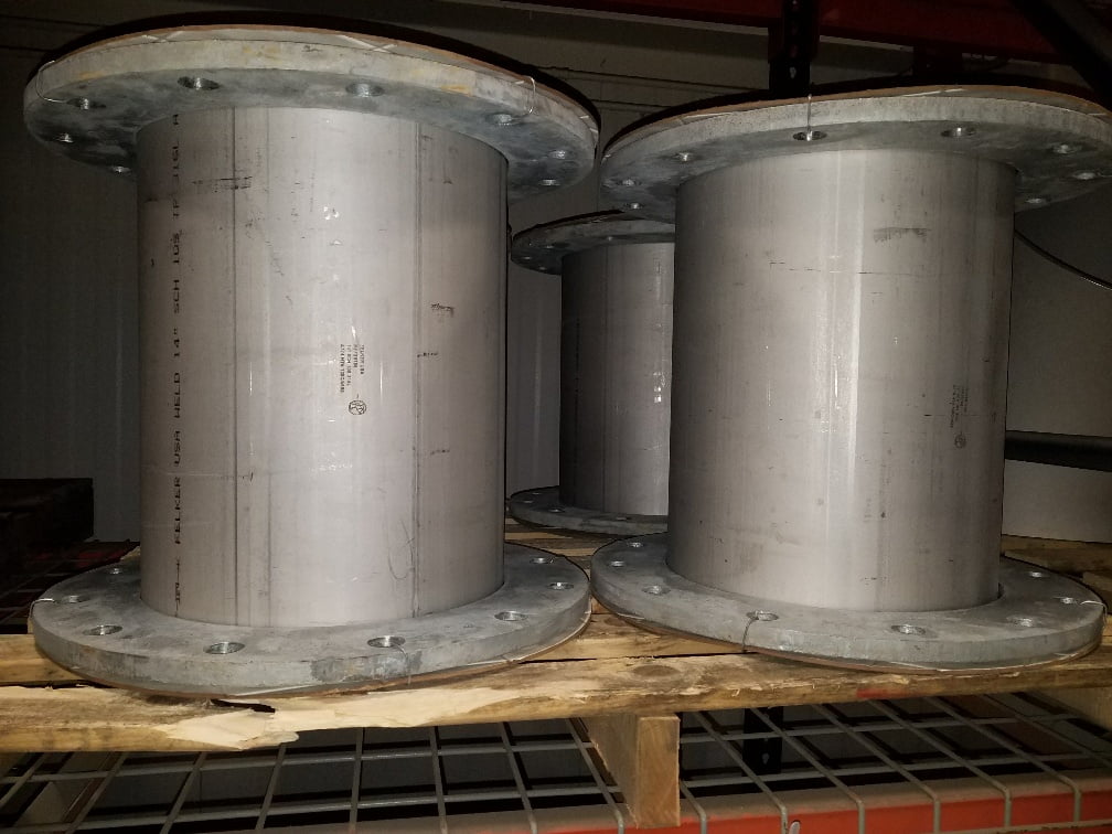
Diameter, length, connections, material and internal geometry are coordinated with the project conditions.
When a vaned-spool review makes sense
A project-specific review may be worthwhile when the suction arrangement includes:
- An elbow, reducer, tee, header or branch connection close to the pump
- Limited straight-run distance before the suction nozzle
- Multiple elbows or an asymmetric piping arrangement
- Unequal flow distribution between similar pumps or branches
- Reported swirl, prerotation or other suspected hydraulic instability
- Noise, vibration or uneven pump performance that may have a hydraulic component
- A new installation or retrofit where the inlet condition needs to be evaluated before fabrication
These conditions do not by themselves establish the cause of a pump problem. They identify information worth reviewing with the pump manufacturer and responsible engineering team.
Not a one-size-fits-all correction
A vaned spool should not be selected from pipe diameter alone. Placement and geometry should be reviewed against the upstream disturbance, pump configuration, operating cases and project criteria.
HOW IT WORKS
Guide the flow through controlled passages.
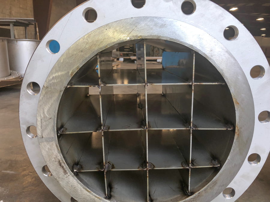
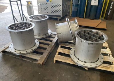
The internal vane grid divides the flow path into smaller passages. Those passages guide the incoming flow through the spool, limiting large-scale cross-flow and rotational motion while promoting a more consistent velocity distribution at the discharge.
The effectiveness of the assembly depends on the upstream disturbance, available spool length, vane geometry, flow range and pump arrangement. A vaned spool cannot correct every pump-system issue, and its use does not replace a full review of the suction system.
When the application warrants additional analysis, Flow Optimizers can coordinate design review, CFD or physical hydraulic model testing.
From application review to fabrication
Each assembly is developed around the project rather than pulled from a generic catalog.
Define the application
Review pump information, operating flow range, suction-piping drawings, available space and the condition the project needs to address.
Develop the geometry
Select or develop the internal flow-conditioning arrangement around the actual approach-flow condition and performance objective.
Detail and coordinate
Prepare approval and production geometry, including spool dimensions, connections, material and project-specific requirements.
Fabricate and document
Coordinate cutting, forming, machining, welding, finishing, inspection and the documentation required for the project.
Specifications & application information
Use the available specification as a starting point, then send the information below so the assembly can be reviewed against the actual project.
PROJECT SPECIFICATION
Inlet Flow Conditioner Specification
Review the available specification language for an inlet flow-conditioning spool assembly.
Confirm suitability, materials, dimensions and acceptance requirements for the specific project.
APPLICATION REVIEW CHECKLIST
What to send with your inquiry
- Pump manufacturer, model and suction size
- Pipe and flange size or applicable connection standard
- Design flow and expected operating range
- Liquid, solids and material requirements
- Upstream fittings, geometry and available straight run
- Installation constraints, drawings and site photographs
- The operating concern or design objective
Send what is available. The Flow Optimizers team can identify any additional information needed for review.
Flow conditioning spools in actual projects
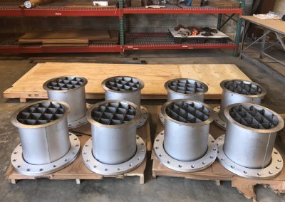
Explore completed assemblies, installations and project-specific flow-conditioning work.
Vaned spool questions, answered
What is a flow conditioning spool assembly?
It is a fabricated pipe spool containing an internal vane or grid arrangement intended to condition flow upstream of a pump suction. The assembly is developed around the piping arrangement, pump and operating requirements.
Where is the assembly installed?
It mounts in the suction piping at a location selected during the application review. Many examples involve double-suction split-case pumps, but the complete arrangement should be reviewed before choosing a location.
Is every vaned spool the same?
No. Diameter, length, flange or connection details, material and internal vane geometry may vary with the project. Final configuration should be based on the actual piping and operating cases.
Can a vaned spool be retrofitted into existing piping?
A retrofit may be possible after reviewing available space, connection details, piping geometry, maintenance access and operating requirements. Drawings and site photographs are helpful during that review.
What information is needed to begin a review?
Start with the pump manufacturer and model, suction diameter, flange details, operating flow range, liquid handled, suction-piping plan and elevation, nearest upstream fittings, available straight run and a description of the issue or design objective.
Does a flow conditioning spool guarantee pump performance?
No. Results depend on the full pump and piping system, operating conditions and the accuracy of the project information supplied. The assembly should be treated as an engineered component within the broader suction-system review.
Is CFD or physical model testing always required?
No. The appropriate review method depends on the complexity, uncertainty and project criteria. Flow Optimizers can help determine whether standard engineering review, CFD or independent physical model testing should be considered.
Start with the piping arrangement.
Send the pump information, operating flow range, suction-piping drawing and the condition you want to address. We will help identify the information needed for the next engineering step.