
ENGINEERING + MANUFACTURING CAPABILITIES
From hydraulic challenge to fabricated solution.
Flow Optimizers brings application review, hydraulic design, CAD modeling, fabrication coordination and project documentation together around one goal: better incoming flow.

A CONNECTED PROCESS
One accountable path from concept through production
A flow-conditioning component has to fit more than a pipe size. It must account for the pump or meter, operating range, piping or basin geometry, available space, materials, installation constraints and project requirements.
Flow Optimizers starts with that full picture. We develop the selected concept, coordinate analysis or model testing when needed, prepare approval drawings and move the design into production with the appropriate fabrication and quality resources.
The process is application-specific, but the objective stays consistent: deliver a practical product that fits the project and addresses the incoming-flow condition.
Capabilities at a glance
Based in
Macon, Georgia
Founded
2017
Core disciplines
Hydraulic design, CAD, fabrication and documentation
Business certification
SBA-certified Women-Owned Small Business
Production
American manufacturing
WHAT FLOW OPTIMIZERS BRINGS TO THE PROJECT
Capabilities built around the application
Each discipline supports the same path: understand the condition, develop the right geometry and produce a workable solution.
Application review
Review pump or meter information, flow range, drawings, geometry, space constraints and the operating issue the project needs to address.
Hydraulic design
Select or develop flow-conditioning geometry around the actual approach-flow condition, installation and performance objective.
CAD drafting & 3D modeling
Develop approval and production geometry using tools that include SolidWorks and Mastercam.
Analysis & model-testing coordination
Coordinate CFD or independent physical hydraulic model testing when the application calls for more than standard design review.
Fabrication coordination
Match the design, material, size and quantity to the cutting, forming, machining, welding and finishing processes required.
Inspection & documentation
Support approval drawings, dimensional review, weld inspection and project-specific submittal requirements.
PRODUCTION RESOURCES
Processes for demanding metal fabrications
The manufacturing route is selected around material, geometry, size, quantity and project requirements. Exact equipment, procedures and production-source qualifications are confirmed for each job.
Precision cutting & forming
- Fiber laser cutting with an eight-section auto-loading tower
- Dynamic waterjet cutting with capacity for sheets up to 6 × 12 feet
- CNC saw cutting
- 250-ton × 12-foot CNC press brake
- Precision sheet-metal fabrication
Machining & production
- Multi-axis CNC machining, including five-axis capability
- Six CNC milling centers and three CNC turning centers
- Manual lathes, mills and surface grinders
- Prototype and contract production-run manufacturing
- CAD/CAM-supported production planning
Welding & finishing
- Fabrication in carbon steel, stainless steel and aluminum
- TIG, stick and spot-welding processes
- Robotic welding capability with reach up to 14 feet
- Media blasting, bead blasting and painting
- Finishing selected around service and project requirements
Quality resources
- FARO Arm dimensional inspection capability
- Approval drawings before manufacturing
- Material and dimensional review
- Weld inspection coordinated to project requirements
- Project-specific documentation and submittal support
EQUIPMENT SPOTLIGHT
Selected fabrication equipment
Reference photos and manufacturer information for two core production resources.

Accurpress Accell U
A 250-ton × 12-foot CNC press brake supporting repeatable forming for sheet and plate components.
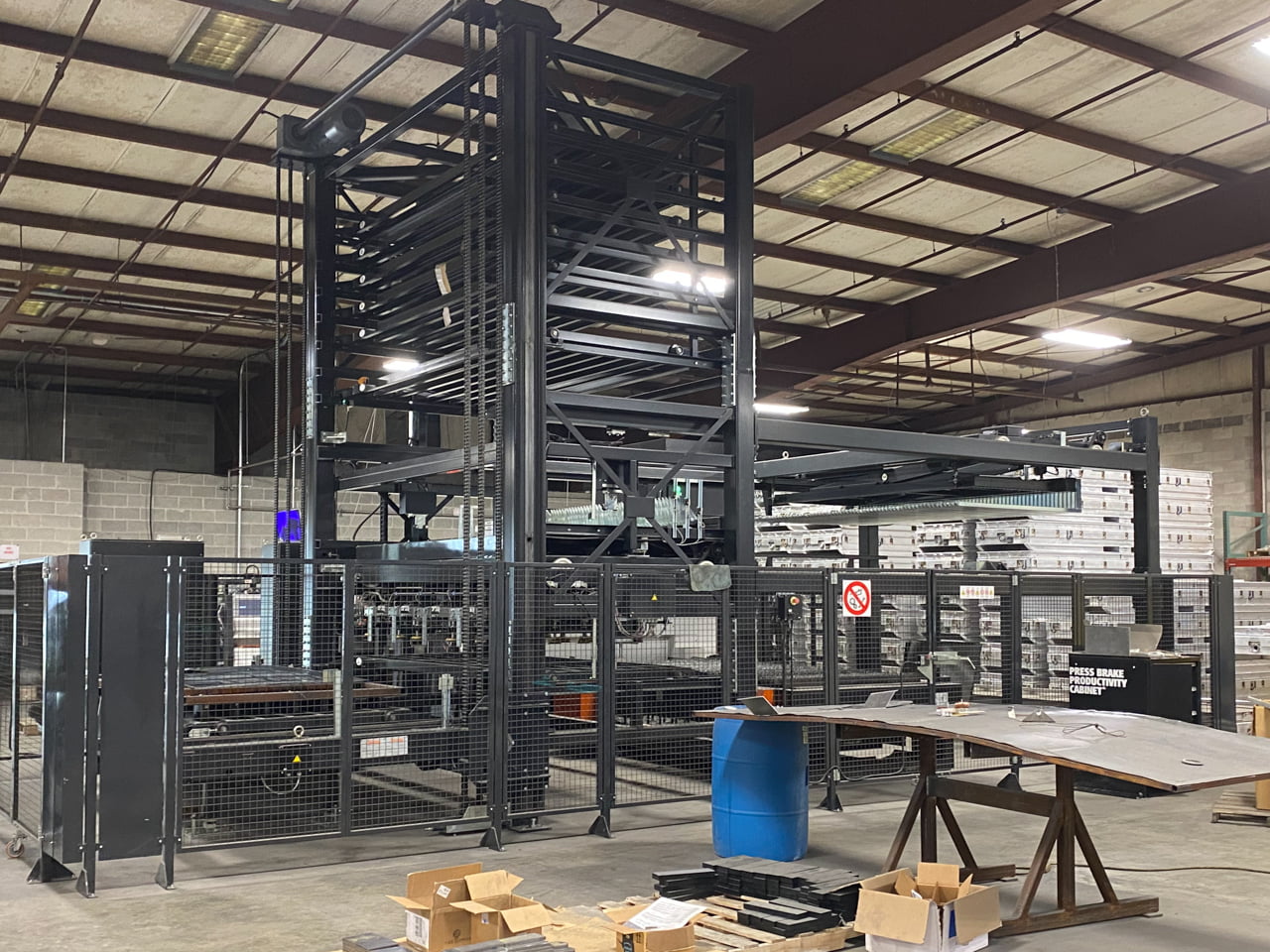
Mazak OPTIPLEX Nexus 3015 Fiber
Fiber-laser cutting with an automation tower for efficient sheet processing and repeatable production.
View the equipment brochure (PDF)
View the 6 kW specification (PDF)

QUALITY + COMPLIANCE
Quality is defined by the project
Flow Optimizer projects can involve application-specific drawings, materials, weld criteria, domestic-content requirements, inspection hold points and final documentation. Those requirements are identified early and carried into approval and production.
- Approval drawings before manufacturing
- Material and dimensional requirements
- Weld and fabrication inspection
- Documentation aligned to project and submittal requirements
- Domestic-content review when specified
Verified business certification: SBA-certified Women-Owned Small Business. Other certifications, registrations, welding qualifications and production controls are confirmed for the specific project and manufacturing source at the time of quote.
Review BABA compliance information / See a documented weld inspection
CAPABILITIES IN ACTION
Recent projects and production updates
See how engineering, fabrication and quality requirements come together on actual Flow Optimizer work.

Flow Optimizers passes stringent weld inspection for Lake Michie vaned pipe spools
Flow Optimizers delivers superior flow solutions through seamless collaboration, rigorous inspections, and unmatched engineering and fabrication excellence.

Flow Conditioning Solutions for Flow Meters
Enhance flow meter accuracy with our Pipe Spools and Flow Inserts, designed to correct flow disturbances and ensure reliable, precise measurements.

Enhance Your Pipeline Efficiency with Flow Optimizer Vaned Elbows and Spools
Boost pipeline efficiency with Flow Optimizer Vaned Elbows and Spools. Improve flow, reduce pressure drops, and save energy in industrial applications.
Tell us what the system is doing.
Share the drawings, pump or meter data, flow range, operating condition and project requirements you have. We will help identify the right next step.